Cnuas Facility Twin is an early-stage experimental extension of Cnuas, being developed as an open-source product. It explores hyperscale data center facility modeling with OpenUSD and NVIDIA Isaac Sim, including scene generation, simplified load calculations and connections to emulated rack telemetry. The prototype will be made available for research and community development.
The campus scene and the emulated racks share one set of figures, so a change in the rack specification moves the load roll-up. Those figures are assumptions carried through arithmetic. Scenario validation, calibration against reference data and the work needed before any engineering use are set out in the roadmap and the limitations below.
Scene generation, configurable illustrative layouts, simplified load arithmetic, and an experimental connection to emulated PSU and BBU telemetry.
It is an exploratory extension, developed in the open beside the Cnuas core and the experimental accelerator stack, with community collaboration intended to carry the work forward.
Physical accuracy, validated power or cooling behaviour, scenario coverage beyond the illustrative cases, production readiness, and suitability for engineering, procurement, safety or operational decisions.
Rendered scenes and passing software tests do not establish a validated model. Emulated telemetry is not measurement from a physical facility, and the Isaac Sim integration exercises the scene rather than the facility assumptions behind it.
plan.plan_campus(),
so it is the same geometry the OpenUSD exporter writes to the stage. The layout is an
illustrative one produced by the prototype, not a facility design. (MP4, 2:14, with narration.)
The illustrative reference campus, default_campus(), is a 1,000 by 800 metre site
holding three datacentre buildings, sixteen data halls, 1,920 racks and a 291 MW load
roll-up. The figures follow from the assumed rack ratings in the built-in catalogue.
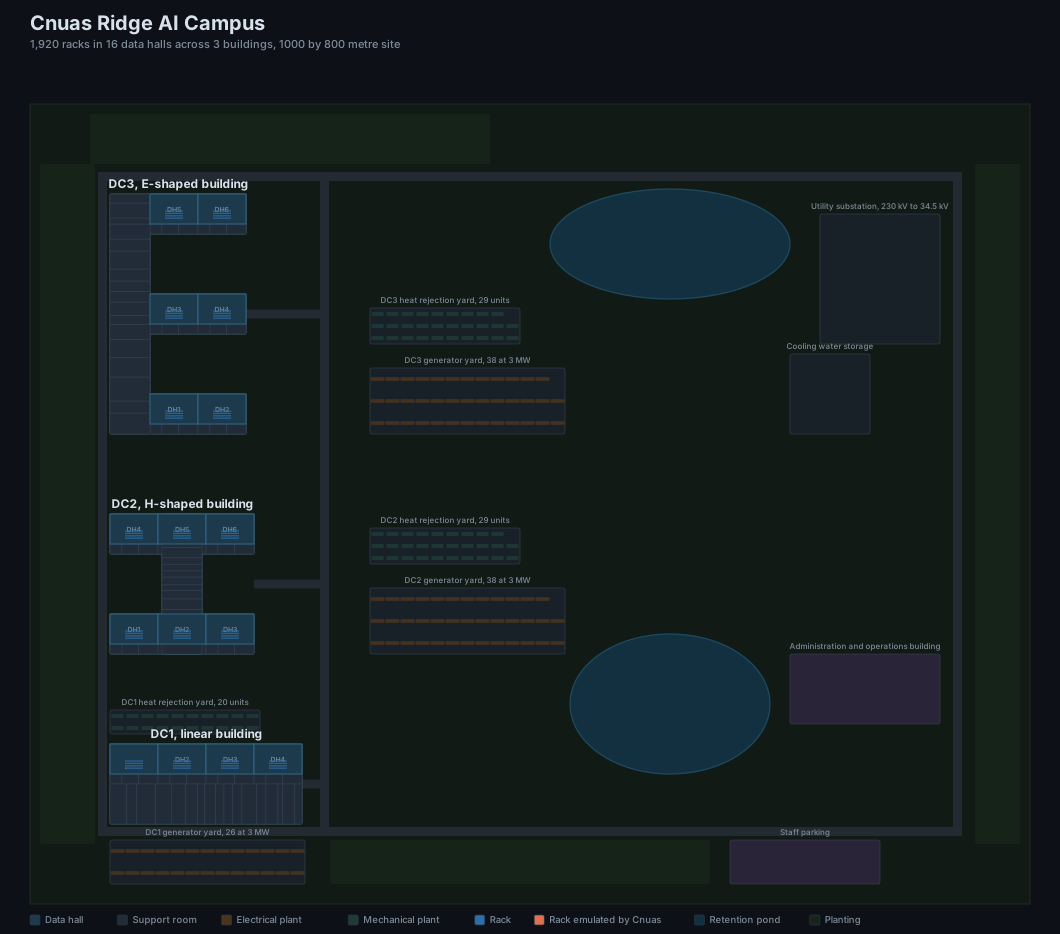
Building forms are not styling. In an H or an E the central spine
carries the electrical and mechanical plant while the data halls occupy the limbs, which is
the reasoning the generator encodes to keep busway runs and pipe headers short. The
prototype places the geometry. It does not size a distribution system.
| Building | Shape | Data halls | Racks |
|---|---|---|---|
| DC1 | I, linear | 4 | 480 |
| DC2 | H | 6 | 720 |
| DC3 | E | 6 | 720 |
Buildings sit west of the north to south service spine. Plant yards, the utility substation, cooling water storage, the administration building and parking sit east of it, which keeps the route from the loading dock to any hall short and leaves a way around every face of every building. Clearances are the generator's own spacing rules, not a check against fire, access or planning codes.
Two retention ponds and four planted screening belts complete the site. They stand in for the stormwater and thermal infrastructure a campus of this size carries, drawn at assumed sizes rather than sized for a catchment.
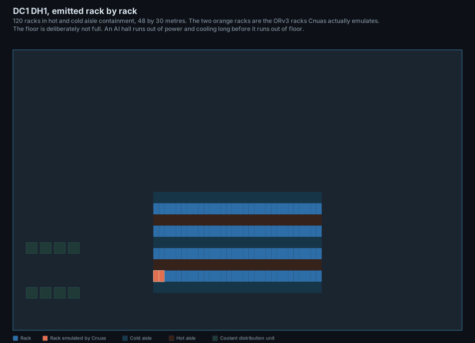
Fifteen of the sixteen halls are emitted as named volumes carrying a rack count and a load. One hall, DH1 in DC1, is emitted rack by rack.
The two emulated racks carry a telemetry attribute on their USD prim:
cnuas:telemetry:source = "modbus-rtu://127.0.0.1:3485/0xc0"
That address is a power supply on the emulated ORv3 power shelf. Reading
PSU_Output_Voltage and PSU_Output_Current from it gives a wattage
that is written back onto cnuas:power:drawKw, so the scene follows the
emulator rather than a fixed number. The reading comes from emulated firmware, not from
an instrument on a physical shelf, and the mapping, units, timing and behaviour under
stale or missing data are among the areas still to be assessed.
The empty area in the plan is not slack. It goes to coolant distribution and to the next phase, because a liquid cooled hall is limited by power and heat rejection rather than by square metres.
Each building carries the TIA-942-B room programme, from the Entrance Room and Meet-Me Room through the Main Distribution Area to the data hall, with a Horizontal Distribution Area, coolant distribution room and fan wall gallery per hall, plus the medium voltage switchgear, transformer vault, paralleling switchgear, battery, pump and water treatment rooms that make a building run. The rooms are placed at assumed sizes. Nothing in the prototype checks them against the standard.
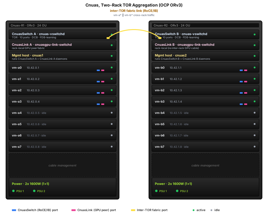
Two racks based on the Open Compute Project Open Rack v3 specifications, each carrying two 1OU top of rack switches, a management host, and eight 2OU blades. Every blade is a guest with an emulated RDMA adapter and one or more emulated accelerators. The whole deployment runs on one workstation.
Change the rack count or the rack type and every figure below moves, including the number of generators. Each one is a roll-up from the assumed ratings in the catalogue, so it shows what the assumptions imply rather than what a built campus would draw.
| Quantity | Value |
|---|---|
| Racks | 1,920 |
| IT load | 253.2 MW |
| Design PUE | 1.15 |
| Facility overhead | 38.0 MW |
| Grid connection | 291.2 MW |
| Heat to reject | 253.2 MW |
| White space | 23,040 m2 |
| Power density | 11.0 kW/m2 |
| Standby generators | 99 at 3 MW |
The campus, the room programme and the load roll-up are produced by the same command line tool that writes the OpenUSD stage. Reproducible means the figures can be regenerated, which is a property of the software rather than evidence about a facility.
Open campus.usda in NVIDIA Isaac Sim, usdview, Blender, or any other USD
capable tool. Isaac Sim and Omniverse are the intended exploration environments, and behaviour
across viewers and versions is one of the things still being worked through. The plans on this
page are regenerated with python3 facility/scripts/render_plan.py.
Those commands rebuild the illustrative reference campus. The planner reads a JSON campus specification, so you can set the site area, the buildings, the halls and rack rows, the cooling and power plant and the grid connection, then have the configuration and the spatial arithmetic checked before anything is exported. Those checks catch a specification that does not fit together. They do not validate an engineering design.
The simulation guide assumes no prior OpenUSD or Isaac Sim knowledge and takes a blank planning worksheet through to an Isaac Sim viewport with live power animation from the emulated ORv3 racks.
The stages below describe the direction of the work. They carry no dates, and none of them is complete. Capability claims on this page will expand only as the supporting evidence exists.
Expose the existing implementation, with its setup requirements, the paths it supports, the assumptions it rests on and the limitations that are known.
Widen the representative layouts, the equipment assumptions and the telemetry integration, and cover abnormal and fault conditions.
Establish traceable datasets, acceptance criteria, calibration procedures and the reporting of uncertainty.
Assess held-out scenarios that were not used to select the assumptions or calibrate the models, and the behaviour of the integrated system.
| Area requiring validation | Work still needed |
|---|---|
| Geometry and catalogue assumptions | Check dimensions, placement constraints, aisle and plant clearances and equipment representations against applicable reference data |
| Electrical, load and thermal behaviour | Compare assumed rack loads, PUE, heat rejection and plant counts with reference calculations and measurements across operating conditions |
| Telemetry integration and faults | Assess mapping, units, timing, stale or missing readings, malformed data, disconnects and fault propagation |
| References and calibration | Establish traceable datasets, calibration procedures, uncertainty bounds and acceptance criteria |
| Held-out scenarios | Evaluate independent scenarios, including abnormal and boundary conditions |
The prototype represents geometry, simplified load and emulated telemetry. It does not perform computational fluid dynamics, electrical fault studies or structural analysis. Building footprints are limited to the I, H and E shapes, and custom configurations can add rack types while the plant item types stay as the built-in catalogue. The Facility datasheet is the reference for all of this.