TORUS-SN ground sensing node¶
Unattended seismic and acoustic ground sensor for AI/HPC data center perimeters. Passive detection, on-device INT8 classification, LoRa 433 MHz uplink, and multi-year endurance on a single primary lithium cell.
Run the power model Node variants
Document status
This page reflects the current design baseline recorded in
docs/TORUS-SN-design-record.md (rev 2026-08-13).
Section 09 records the earlier
pre-production board and the full supersession list. Endurance and capacitor
figures are
planning-model outputs and are not released as guaranteed specifications
until the bench measurements in section 08 close.
01 · Description¶
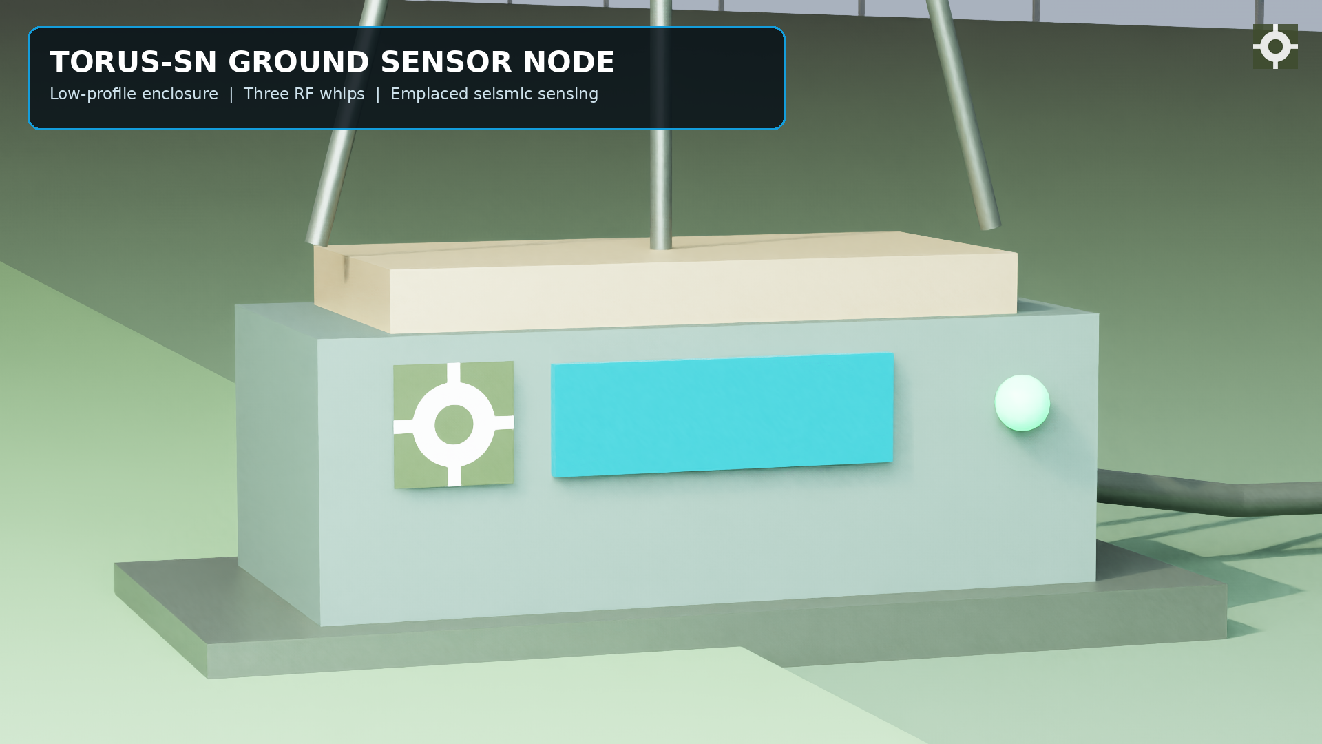
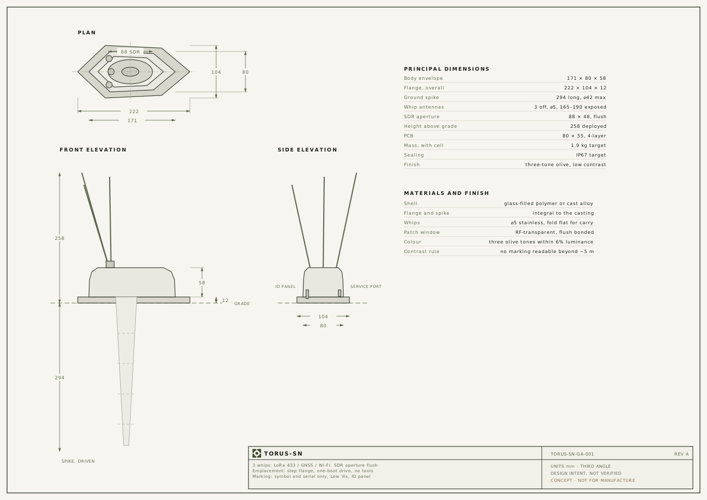
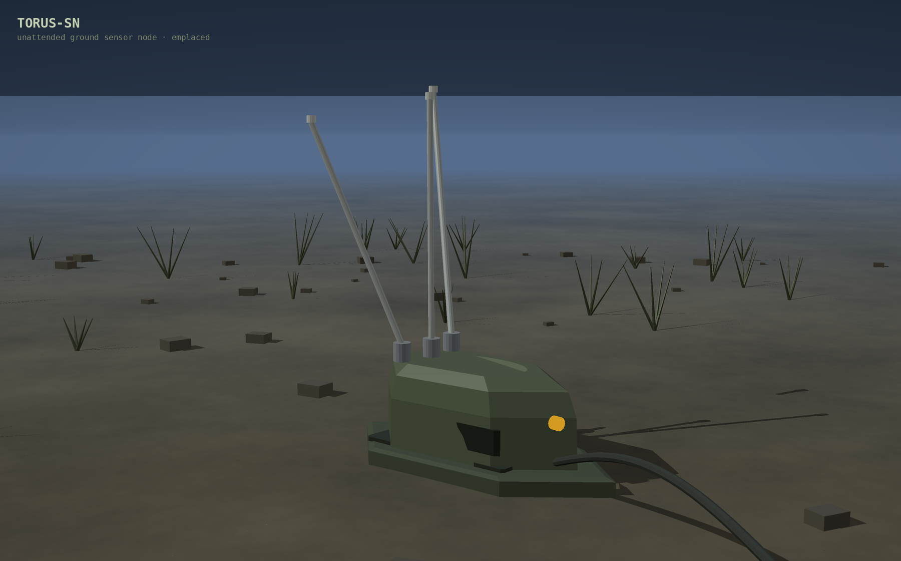
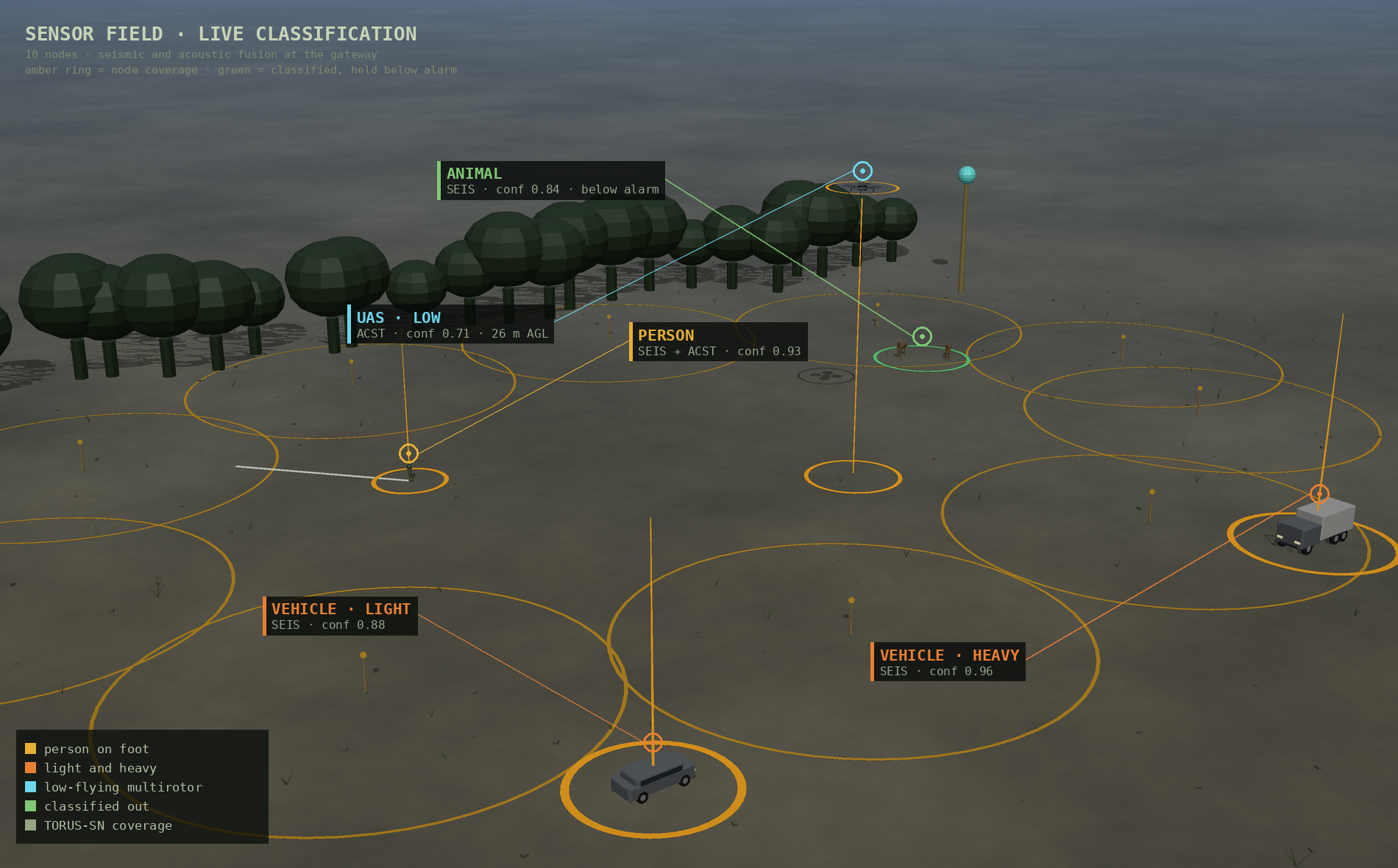
TORUS-SN is the ground sensing element of the TORUS UAGVIS platform, Unattended Air-Ground-Visual Sensing. It watches a length of campus perimeter, service yard, or data hall approach for footfall, vehicles, and digging, classifies what it hears and feels on the node itself, and reports a compact labelled event over LoRa to a TORUS-MEG gateway.
The node emits nothing except its own short uplinks. Detection is entirely passive: a vertical geophone and two MEMS microphones. Always-on monitoring runs in hardware, so the processor stays in Stop 2 at 1.6 µA until a threshold is crossed.
Features¶
- Passive dual-domain sensing, 4.5 Hz vertical geophone plus a stereo pair of 24-bit MEMS microphones. No emitted energy from the sensing path.
- Zero-processor always-on watch, TDK T5848 Acoustic Activity Detect runs inside the microphone at 20 µA per part, and an on-die comparator watches the seismic threshold, both with the core asleep.
- On-device INT8 classification, statically generated CMSIS-NN inference on the Cortex-M33. Audio is classified at the node; raw audio never leaves it.
- One radio, three services, LR1120 provides LoRa 433 MHz uplink, passive Wi-Fi AP-scan positioning, and multi-constellation GNSS in one package, with an S-band branch laid out for non-EU builds.
- Self-locating, a relocated node reports its own new position from GNSS or Wi-Fi scan, so a moved or disturbed node is detected.
- Multi-year primary-cell endurance, 3.7 years at the reference profile, over 10 years in the stealth profile, on one Saft LS 33600.
- Per-block power gating, every sensing element sits behind its own high-side switch and can be disabled remotely over LoRa downlink.
- Security by construction, TrustZone separation on the host and AES-128 hardware crypto in the radio.
02 · Block diagram¶
Sense · seismic
R.T. Clark 4.5 Hz geophone, 395 Ω
- ADS1220 24-bit, 2 kSPS, 415 µA
- MCP4017 digipot sets threshold
- on-die COMP1/COMP2 wake in Stop 2
- high-side switch power gating
Sense · acoustic
2 × TDK T5848 I2S MEMS
- AAD analogue 20 µA always-on
- low power 130 µA / high quality 330 µA
- 68 dBA SNR, 133 dB AOP
- 1.8 V rail from dedicated LDO
Host
STM32U575xxQ Cortex-M33 @160 MHz
- TrustZone, FPU, 240 DMIPS
- up to 2 MB flash, 786 kB SRAM
- LPBAM autonomous DMA to Stop 2
- Stop 2 + RTC 1.6 µA
Vector math · gated
Lattice iCE40 UP5K
- 5280 LUT, 8 × 16×16 DSP, 128 kB SPRAM
- 62 µA static
- retained only on a non-power justification
- see section 8.1
Radio and position
Semtech LR1120 QFN32
- sub-GHz LoRa 150–960 MHz, −148 dBm, to +22 dBm
- 2.4 GHz LoRa, S-band 1.9–2.2 GHz (DNP on EU)
- passive Wi-Fi AP scan, multi-GNSS
- 32 MHz TCXO, GNSS LNA, PE4259 SPDT
Power
Saft LS 33600, 3.6 V, 17 Ah Li-SOCl2
- ideal-diode reverse blocking
- soft-start switch into ≥470 mF supercap
- buck-boost to 3.3 V, ~11 µA quiescent
- BQ35100-class coulomb-counting gauge
Rails: 3.3 V to host, radio, and ADC direct; 1.8 V LDO for the microphones; 1.2 V for the FPGA core if retained. Every block sits behind a high-side switch.
03 · System summary¶
| Function | Part | Key figures |
|---|---|---|
| Host MCU | STMicroelectronics STM32U575xxQ | Cortex-M33 @160 MHz, TrustZone, 2 MB flash, 786 kB SRAM, 6.55 mA CoreMark typical, 1.6 µA Stop 2 + RTC, 1.71–3.6 V |
| Radio | Semtech LR1120 | LoRa 150–960 MHz + 2.4 GHz + S-band, −148 dBm, +22 dBm max, Wi-Fi AP scan, multi-GNSS, AES-128, 1 µA sleep |
| RF support | 32 MHz TCXO, GNSS LNA, PE4259 SPDT | TCXO mandatory for GNSS; RFSW pins drive the switch and LNA directly, never through host GPIO |
| Microphones | 2 × TDK T5848 | I2S 24-bit PCM, 3.5 × 2.65 × 0.98 mm, 1.62–1.98 V, AAD 20 µA / LP 130 µA / HQ 330 µA |
| Geophone | R.T. Clark 4.5 Hz vertical, 395 Ω | Useful bandwidth to ~200 Hz; footfall, vehicle, and digging signatures |
| Geophone ADC | Texas Instruments ADS1220 | 24-bit, 2 kSPS, 2.3–5.5 V single supply, 415 µA active, 0.5 µA power-down |
| Threshold set | Microchip MCP4017 digipot + on-die COMP1/COMP2 | 128-step gain; comparator wake active in Stop 2 |
| Vector math | Lattice iCE40 UP5K gated | 5280 LUT, 8 DSP, 128 kB SPRAM, 62 µA static, 96 MMAC/s @12 MHz |
| Cell | Saft LS 33600 D cell | Li-SOCl2 primary, 3.6 V, 17 Ah, 33.4 × 61.6 mm, ~100 g, <1%/year self-discharge, −60 to +85 °C |
| Pulse buffer | ≥470 mF low-leakage supercap + TPS22919 soft start | Sized from battery-side current; ≤3 µA leakage target |
| Conversion | Buck-boost to 3.3 V | ~11 µA quiescent; holds 3.3 V across the 3.6–3.0 V discharge curve |
| Fuel gauge | TI BQ35100 class | Coulomb counting; Li-SOCl2 voltage curve is too flat for voltage-based gauging |
| Protection | Ideal-diode reverse-current blocking | Mandatory on the converter input, gauge path, and any auxiliary or USB path |
Rated cell current is 250 mA continuous and 400 mA pulse, derated per design rule to 100 mA continuous. UN 3090/3091 Class 9 hazmat applies to transport.
04 · Configuration profiles¶
Profiles are selected at deployment and are remotely reconfigurable from the gateway over LoRa downlink. Every sensing element is independently power gated, so a profile is a rail and duty-cycle policy rather than a firmware build.
| Profile | Configuration | Battery equivalent | Endurance |
|---|---|---|---|
| Stealth | Seismic only, microphones disabled, Wi-Fi off, LoRa wake-on-radio only | ~0.05 mA | 10+ years, shelf-life limited |
| Standard | T5848 AAD analogue, seismic gated, Wi-Fi 5 min, heartbeat 15 min | ~0.22 mA | ~8 years |
| Patrol | T5848 AAD analogue, Wi-Fi 30 s, heartbeat 5 min | ~0.40 mA | ~4.4 years |
| Alert | T5848 low power mode, Wi-Fi 10 s, heartbeat 1 min | ~0.83 mA | ~2.1 years |
| Lockdown | T5848 high quality streaming, all sensors continuous, maximum reporting | >5 mA | Months |
Reference profile for the headline figure is moderate environment, sensitivity 5/5, one trigger per minute, 10 inferences per trigger, 500k-MAC INT8 model: 0.471 mA battery-equivalent, 1.55 mW average, 3.71 years. The vector unit's 0.062 mA static draw accounts for 0.067 mA of that at the reference inference rate.
05 · Power model constants¶
Currents are given at the regulated 3.3 V rail unless stated. Lower-voltage loads are represented by their 3.3 V input-current equivalent including local regulator loss. Rail loads are converted to battery-equivalent current using Pout / (Vcell × efficiency); cell-side quiescent and leakage currents are added directly. (E) marks an estimate pending measurement.
| Block | State | Current (mA) |
|---|---|---|
| STM32U575 | Stop 2 + RTC | 0.0016 |
| STM32U575 | Run 160 MHz, SMPS, CoreMark typical | 6.55 5.10–7.35 workload range; 14.0 design max at 30 °C |
| iCE40 UP5K | Static | 0.062 |
| iCE40 UP5K | Inference active | 1.8 (E) |
| T5848 | AAD analogue, each | 0.020 |
| T5848 | Low power / AAD D1, each | 0.130 |
| T5848 | High quality, each | 0.330 |
| ADS1220 | Active | 0.415 |
| ADS1220 | Power-down | 0.0005 |
| LR1120 | Sleep | 0.001 |
| LR1120 | Sub-GHz RX | 5.7 |
| LR1120 | TX +10 dBm | 25 |
| LR1120 | TX +22 dBm | 118 |
| LR1120 | Wi-Fi AP scan | 12 (E) |
| LR1120 | GNSS scan | 12 (E) |
| Buck-boost | Quiescent | 0.011 (E) |
| Fuel gauge | BQ35100 class | 0.010 (E) |
| On-die COMP | Threshold watch | 0.001 |
| Supercap | Leakage | 0.003 |
Throughput: iCE40 UP5K at 12 MHz across 8 DSP blocks is 96 MMAC/s; STM32U575 M33 at 160 MHz with CMSIS-NN is about 150 MMAC/s (E). Battery 17000 mAh nominal, 90% usable assumed, 3.3 V average cell, 90% conversion efficiency.
Reading the STM32 numbers correctly
Operating figures are from ST DS13737 Rev 10 §5.3.6. Table 43 gives 5.10–7.35 mA typical at 160 MHz and 3.3 V depending on workload; Tables 38–39 give 14.0 mA maximum at 30 °C. Table 30's 100/200 mA values are absolute-maximum pin and package current limits, not operating consumption, and must not be used as a power input. LR1120 Wi-Fi and GNSS are scan engines rather than continuous receivers, so their 12 mA planning constants stay conservative and estimated until the selected radio firmware mode is measured.
Open the interactive power calculator
06 · Radio, airtime, and regulatory¶
The radio holds full TX or RX current for the whole time-on-air, so frame size and spreading factor drive radio energy more than TX power does.
| Spreading factor | Time on air, 20-byte payload | Energy at +10 dBm |
|---|---|---|
| SF7 | 56.6 ms | 1.4 mA·s |
| SF9 | 185.3 ms | 4.6 mA·s |
| SF10 | 370.7 ms | 9.3 mA·s |
| SF12 | 1318.9 ms | 33.0 mA·s |
BW 125 kHz, CR ⅘, explicit header, CRC on, 8-symbol preamble.
Frame design guidance¶
- Keep the payload short. Airtime scales with payload length.
- Adaptive spreading factor per node, fixed at commissioning from measured RSSI. Uniform SF12 would cost 23× more radio energy on near nodes.
- Batch. The preamble is 12.25 symbols regardless of payload; at SF12 that is 401 ms before a single data bit moves. One 40-byte frame beats two 20-byte frames by roughly 30%.
- Coding rate stays ⅘ unless a site survey shows burst errors. Raise SF for weak signal, raise CR for interference.
Regulatory coupling
EU 433.05–434.79 MHz under ERC REC 70-03 is generally 10 mW ERP with a 10% duty cycle, and some sub-bands are 1 mW. At SF12 the 10% limit caps transmission near 273 packets per hour, costing about 2.5 mA. The regulatory ceiling and the affordable power ceiling land in nearly the same place. Confirm the sub-band against current ETSI EN 300 220 before fixing the PA design.
Sensitivity and trigger model¶
Detection thresholds are logarithmic against a noise floor, so trigger rate grows
exponentially with sensitivity:
triggers/hr = env_base × 2.2^((sensitivity - 1) / 2), with env_base of 1.5
quiet, 8 moderate, and 35 noisy. Seismic runs at half the acoustic rate.
Sensitivity is cheap, precision is not
At the reference profile, inference is under 0.5% of the budget. Even at a noisy site with both sensitivities at 10, roughly 1824 triggers per hour, vector duty reaches only about 2.6% on the FPGA or 1.7% on the host. What threatens the budget is false positives reaching the radio: 182 transmissions per hour at SF12 and +10 dBm is 1.67 mA at the 3.3 V rail, which alone would exceed everything else combined and would breach the EU duty cycle limit.
Design consequence. Run the sensors sensitive, because triggering is cheap. The classifier's job in power terms is to stop false positives becoming transmissions. Tune the confidence threshold for transmit, not the sensor threshold, and require N consecutive positive frames before any report.
07 · Firmware and AI toolchain¶
The production node path is a statically compiled INT8 inference pipeline, not a general-purpose tensor runtime. Generated model code and weights are linked into the Zephyr firmware image. There is no filesystem model loader and no dynamic operator registry on the node.
| Stage | Tool |
|---|---|
| Training | PyTorch |
| Interchange | ONNX with fixed input shapes |
| Quantization | INT8 against representative site data |
| Code generation | STM32Cube AI Studio |
| MCU kernels | CMSIS-NN where supported |
| Reference comparison | TensorFlow Lite Micro + CMSIS-NN, host side only |
| RTOS | Zephyr |
Model sizing¶
| Architecture | MACs | UP5K time | UP5K energy | U575 time | U575 energy |
|---|---|---|---|---|---|
| Tiny 1D CNN (transient) | 50k | 0.5 ms | 0.003 mJ | 0.3 ms | 0.007 mJ |
| Autoencoder (anomaly) | 264k | 2.8 ms | 0.016 mJ | 1.8 ms | 0.038 mJ |
| Small 2D CNN (mel) | 500k | 5.2 ms | 0.031 mJ | 3.3 ms | 0.072 mJ |
| TCN (dilated causal) | 1.2M | 12.5 ms | 0.074 mJ | 8.0 ms | 0.173 mJ |
| DS-CNN (MLPerf Tiny KWS) | 5.4M | 56.0 ms | 0.333 mJ | 36.0 ms | 0.778 mJ |
If the FPGA is retained, 128 kB of SPRAM caps INT8 weights near 100k parameters with room for activations, ruling out the DS-CNN row. If the FPGA is dropped, 786 kB of host SRAM removes that constraint.
Task mapping¶
Drone acoustic · pure DSP baseline available
Harmonic stack whose fundamental tracks rotor RPM at 150–200 Hz with harmonics to several kHz. Small 2D CNN on a mel spectrogram; try harmonic product spectrum plus threshold first, since that needs no training data.
Footstep and vehicle · seismic channel
1D CNN or TCN on the raw seismic waveform. TCN parallelises cleanly; GRU and LSTM need recurrent state that fits awkwardly in fabric.
Unknown anomaly · site-adaptive
Autoencoder on a quiet-site baseline, scoring reconstruction error. This is what makes deployment training mode valuable: it learns what normal looks like at that specific site.
ggml is not part of the node runtime
ggml is a useful cross-platform tensor library for substantially larger CPU and GPU-class workloads, but its runtime, graph, and tensor abstractions do not improve this fixed-shape, sub-megabyte Cortex-M inference case, and it cannot be synthesized into an iCE40 datapath. TensorFlow Lite Micro is permitted for host reference comparison and early board bring-up, but its interpreter and operator resolver are not part of the production TORUS-SN image.
Full three-tier inference architecture: AI/ML engine.
08 · Open gates¶
Two gates are open against this baseline. Both are blocking, and endurance and capacitor figures on this page remain planning-model outputs until gate 8.2 closes.
8.1 Blocking, does the iCE40 UP5K stay in the design¶
With T5848 Acoustic Activity Detect handling always-on acoustic monitoring at 20 µA, the FPGA has no continuous workload. It costs 62 µA static and saves about 12.46 µA·s per inference under the corrected CoreMark-proxy host assumption.
| Configuration | Battery equivalent | Endurance |
|---|---|---|
| Without iCE40 UP5K | 0.404 mA | 4.32 years |
| With iCE40 UP5K | 0.471 mA | 3.71 years |
Breakeven is 31× away
0.062 mA × 3600 s / 0.01246 mA·s ≈ 17,900 inferences/hr, about 5 per second
sustained. The specified reference profile runs at 580 inferences per hour,
roughly 31× below breakeven. On power alone the FPGA should be removed.
Retaining it needs a non-power justification: deterministic inference latency,
a model too large for host SRAM, or headroom for a future modality. Decide
before schematic freeze.
The published site figures (0.471 mA and 3.71 years) are the FPGA-retained case, so the headline endurance is the conservative one either way.
8.2 Blocking, close the power model on hardware¶
The calculator separates rail current from battery-equivalent current and exposes host workload, cell voltage, and conversion efficiency, but it remains a planning model. Before endurance or capacitor claims are released as guaranteed specifications, measure:
- STM32U575 current running the actual CMSIS-NN model with its real clock, cache, memory, SPI, and DMA configuration.
- Generated code, weights, activations, and sensor buffers fitting with at least 25% flash and SRAM margin.
- Bit-exact test vectors from the quantized training export through the generated node implementation.
- Inference latency and rail energy across voltage and temperature.
- Deterministic non-ML threshold behaviour for safe degradation.
- Regulator efficiency and quiescent current over cell voltage, temperature, and the relevant load range.
- LR1120 sub-GHz RX, Wi-Fi scan, and GNSS scan current and duration for the exact radio firmware modes.
- Simultaneous rail and cell current during TX, RX, and startup.
- FPGA core, I/O bank, configuration, and model-load energy if it is retained.
8.3 Secondary verification items¶
- iCE40 UP5K active current with the real pipeline, modelled at 1.8 mA and never measured. Only matters if 8.1 retains the FPGA.
- 433 MHz matching network values for the LR1120. Reference designs are 868/915 MHz and do not transfer.
- Rail sag during LoRa TX at −20 °C on a partially discharged cell, with and without the supercap fitted.
- Exact EU 433 sub-band power and duty limits against current ETSI EN 300 220.
- Classifier precision from training mode, which becomes the largest single term in the budget once known.
- T5848 AAD false-trigger rate at each threshold setting in the target acoustic environment.
Safety-critical constraints¶
Three constraints that are not negotiable
- A discharged supercapacitor presents a short circuit to a Li-SOCl2 cell. It cannot be hard-wired across the cell; inrush must be limited by a soft-start switch.
- Reverse current into a primary cell is charging it, which is a fire and explosion hazard. Blocking is mandatory on the buck-boost input, the fuel gauge path, and any USB or auxiliary connector path.
- T5848 absolute maximum supply is 1.98 V. It must not be fed from the 3.3 V rail; a 1.8 V LDO is required.
09 · Superseded pre-production board¶
A complete pre-production PCB exists and was fully generated, routed, and released to fabrication outputs: an 80 × 55 mm 4-layer board with 91 parts and 68 nets. The 2026-08-13 design record supersedes it. It is recorded here because it is what was actually fabricated, and bring-up data from it feeds the baseline.
| Function | As built (pre-production) | Baseline (current) |
|---|---|---|
| Host | STM32U575xxQ | |
| Radio | Semtech LR1120, S-band branch DNP on EU units | |
| Geophone ADC | ADS1220, 3.3 V, 415 µA | |
| Threshold comparator | On-die COMP1/COMP2 on the host | |
| Microphones | 2 × TDK T5848 with AAD | |
| Geophone AFE | Integrated in the ADS1220 front end | |
| Timekeeping | Host RTC in the VBAT domain | |
| Cell and charging | Saft LS 33600 Li-SOCl2 primary, buck-boost | |
| RF switching | PE4259 SPDT | |
| Vector math | iCE40 UP5K gated |
Carried over unchanged¶
PE4259 SPDT RF switch on the LoRa PA path, buck-boost to 3.3 V, high-side switches for per-block power gating, MCP4017 digipot setting the comparator threshold, the auxiliary connector carrying WAKE / INT / UART / USB, and the FT231 debug UART header (power-gated or depopulated in production).
Added at baseline¶
A 1.8 V LDO for the T5848 rail, ideal-diode reverse-current blocking on all cell-facing paths, a ≥470 mF low-leakage supercapacitor with a soft-start switch, and a coulomb-counting fuel gauge of the BQ35100 class.
Also retired¶
The STM32WL55CC candidate was retired because the LR1120 is mandatory in every configuration for its Wi-Fi scan and GNSS engines, which makes an on-die sub-GHz radio in the host redundant. That also retired the dual-core requirement: the M0+ on STM32WL exists to isolate the sub-GHz MAC stack, and with the radio on SPI there is no stack to isolate. TrustZone on a single M33 covers the separation.